Table of Contents
The DL0100A1 (DLITE0100A1) hardware is also compatible with the family of Connect modules from Digi International, including the ME (rectangular enclosed modules) and EM (exposed PCB, lower profile, flat-ish) series, both available in standard (Ethernet) and “Wi-” versions (WiFi). Power-over-Ethernet (PoE) is also supported. This article presents manufacturer links, and implementation information basics. “CME” refers to the basic series of Ethernet, enclosed/shielded modules. This is article draft 0, a quick sketch.
Connect ME (CMD) Module Resources and Basics
The manufacturer, Digi International, regularly updates their website structure, so links here may not work, or may not be current. Search their website for relevant documents if the links here do not work.
While the general pinout and functionality is similar across all CME devices, there are some differences, depending on the specific part number or module that you are using. So, it’s useful to verify your part number and standard in-house implementation of the module on the DL0100A1 hardware. You may also have an older module that requires some legacy documentation for very specific details. However, the pinouts generally are the same.
Plug-n-play firmware devices mean that they ship ready to drop in and implement a standard interface that you access via network cable and login because they have an embedded web server and protocol handler (API) for setting the network and functional configuration of the module, its pins, etc. An API is available on these modules as well for sending remote command interface (RCI) configuration and functional commands over the network, remotely. You can authenticate and configure pin states for example, using RCI too. This can be used to implement the control of the main DL0100A1 power rail to the rest of the board for example. There are detailed manuals for the RCI specification as well as other aspects of the module and standard Digi systems and/or protocol implementations.
Links, ss of 2020-09-Sep:
- Digi link: Connect ME Family page: https://www.digi.com/products/embedded-systems/system-on-modules/digiconnectme9210#partnumbers
- Digi link: Connect ME Plug-n-Play device, single pack: https://www.digi.com/products/models/dc-me-y402-s
- Digi link: Connect ME datasheet: https://www.digi.com/pdf/pb_digiconnectme9210.pdf
- Digi link: Connect ME user guides and manuals: https://www.digi.com/products/embedded-systems/system-on-modules/digiconnectme9210#productsupport
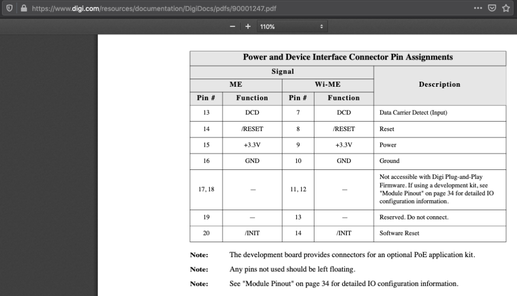
- Digi link: Connect ME hardware reference manual: https://www.digi.com/resources/documentation/DigiDocs/pdfs/90001247.pdf


Module Connector Implementation on the DL0100A1
For additional information regarding default jumper positions and power management on the DL0100A1, please use the search bar on this site to locate other articles, or for example, see: https://oshablue.com/doc/dlite0100a1-jumper-shunt-settings/
Defaults
By default, that is, populating the board with the default components, specifically, installing R71, and leaving unpopulated: R69 and R70, the XBee device can use its DIO1 pin to control main hardware power rail, if the JP7-VDDEN is set accordingly. A CME device can control the main hardware power rail, again depending on the JP7-VDDEN setting, with its DIO0. Using DIO1 on the XBee and DIO0 on the CME, versus using the same pin designation on each module is due to slight differences in implementation that required DIO1 on the XBee and DIO0 on the CME.
If R70 is installed, then a CME type of module or an XBee can control the DL0100A1’s main power rail with DIO12 (again, if JP7-VDDEN is accordingly set to allow this).
For UART communications to/from the MCU on the DL0100A1, the Rx/Tx pins are implemented as noted in the stock Digi plug-n-play firmware, and also are connected to the same Rx/Tx pins on the XBee footprint. The same it true for !CTS.
There are a large number of potential configurations and implementations both on the Digi module and on the DL0100A1 hardware, so please send specific questions if/as needed.
You may need to log in to the module or use RCI configuration to set the UART configuration, speed, etc.
Testing / Troubleshooting
Your needs for testing and troubleshooting may be highly dependent on details of your use-case and steps taken to configure or modify hardware population, firmware, or configuration settings. So, it is useful to be specific about what functionality has changed when you are chasing down use-case testing glitches. A checklist, to start:
- Is the CME module itself powered up? LEDs with a live network cable connected lit up?
- Can you log into the CME over the network?
- If not, do you know the last known CME network settings? This is important. The module may need a reset if it was set to an unknown network subnet or IP or if DHCP was turned off etc., and you are not able to talk to it from your PC.
- Use something like Wireshark to watch for packets coming from the CME module – note its MAC address and filter to search from packets from that CME, and then you’ll be able to assess network settings from there.
- Once you can log in to the module, check the pin functionality, especially the default UART settings.
- If you are trying to connect as a COM port device using the Digi virtual UART driver for the CME, there are several settings to check there and ensure that the module is set up to be a virtual UART device, that its IP and network settings are right and match, etc. There are details available in many places on the Internet to do this. Or try re-installing as this will re-start the attempt at auto-detecting the CME module, perhaps using the Digi virtual CME module detection protocol, or however that is implemented.
- Make sure your power configuration is correct, such that the board itself, via the main power rail control, is powered up, thus allowing the CME module to actually talk to the MCU etc that is powered up and healthy.
- If you have questions, help is available, please be specific about the scenario to expedite support for you.