Table of Contents
The ADMPlex interfaces directly on the DL0100A1 board, matching its form factor, and hosts up to four (4) separate ADMM client boards.
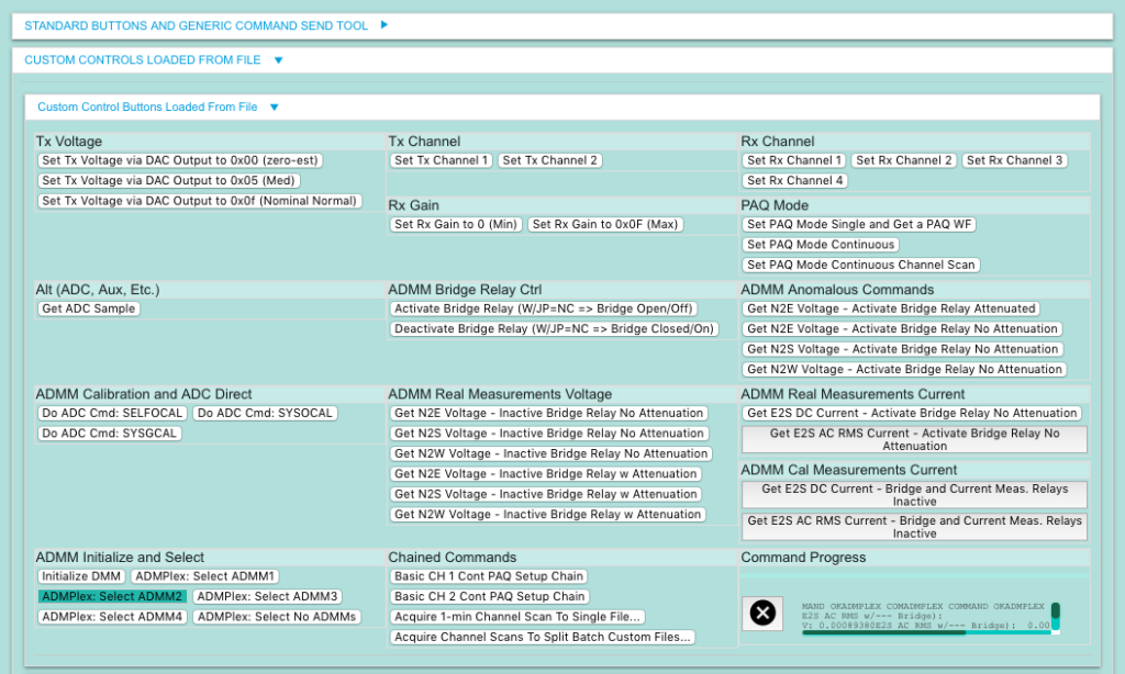
ADMM boards require a single (JP2/4) connector retrofit that simplifies wiring and jumper requirements for the assembly. LED indicators duplicate the DL0100A1 main LED indicators and indicate the currently selected ADMM. Additional LEDs and GPIOs are available for whatever additional functionality you want to add on. DacqMan shows example commands that interface with an update to the main DL0100A1 firmware to talk to each of the 4 ADMMs hosted. There is an MCU on the ADMPlex that also requires firmware (pre-installed) and can updated to modify and add functions as needed.
For discussion and documentation, the board orientation is as if the board were stacked on a DL0100A1 with the SMA connectors pointing left. Thus the ADMPlex main 2-terminal power screw terminal block is at the North-East (NE) and the cluster of the ADMM-selection LED indicators, the auxiliary R/G/B LEDs and the MCU ICSP shrouded header is at the South-West (SW).
Power

LEDs

Left most RED = #1, left-from-center GREEN = #2, right-from-center RED = #3, and right most GREEN = #4.
LX4 (Blue), LX5 (Green), and LX6 (Red) are available for implementation in firmware, mapped to MCU signals RA7, RA6, and RA4 respectively.

ADMM Retrofit to JP2/4
A retrofit of the ADMM board for use with the ADMPlex is required. The 5-pin (comprising a 2 + 3 pin pair of headers) header that is used for a jumper/shunt and the power input wiring in other use cases must be replaced with a female-male through header, like part Samtec SSQ-105-03-G-S or similar. This replacement then mates with the matching header on the ADMPlex to provide power as well as the jumper/shunt functionality for the ADMM board.
Control Sequence Best Practice & Order of Operations
Maybe you already have a specific order of operations in place to guarantee a known idle state without energized relays. In any case, something like the order of operations below is probably more important in the ADMPlex to prevent the increase of idle current due to relays remaining energized after making measurements with a board.
- Select the target hosted ADMM
- Initialize the ADMM
- Take readings as needed
- Initialize the same ADMM or use a specific command to de-energize all relays
- THEN switch to a new ADMM, starting at step 1 above.
Typical Values and Behavior

Options for DL0100A1 and Other Retrofits
Various component replacements or retrofits may be desirable to make it easier to disconnect power wires from the main DL0100A1 board for example, among other things.
The main power interface screw terminal block on the DL0100A1 uses upward facing heads. This block can be replaced with a screw terminal block with side-facing screw heads or a screw terminal block system that uses a side-entry plug. Examples:


DL0100A1 Programming (DPA = DL Programming Adapter)
By design, the ADMPlex covers the DL0100A1 ICSP footprint. A clip-on right-angle programming adapter, “DL0100A1 Programming Adapter (DPA)”, is available has been validated and is available to allow programming and debugging without disassembling the board stack.
Updating the ADMPlex MCU’s Firmware

QA/Validation Test Conditions
A bench power supply and/or battery pack was used to generate the static (DC) voltage and current conditions, with the current passing through the normally closed bridge and a few resistors. Depending on the voltage and resistors selected, you may want to switch the current measurement jumper to the uA position, even if just to validate.
| Battery or power supply source | |
| North | |
| 37k resistor | |
| East | |
| Bridge | |
| South | |
| 14.6k resistor | |
| West | |
| 37k resistor | |
| Battery or power supply return |
Important Reminders
Calibration
Calibration is important. Both for the general system input to output voltage validation, and for specific boards.
Time-Dependent Measurements
For some measurements, the first measurement, right after relay activation, may not have yet reached steady-state for an accurate measurement at the ADC terminal.
Alternatively, some measurements with environmental time-dependent effects may actually be more accurate within some initial measurement time window.
The ADMM boards have configurable components and parameters to select their time response.
DacqMan

GPIOs

Connectors, Standoffs (Spacers), and Board-to-Board Spacing
Please measure and verify these spacings. There are variations that depend on your needs.
DL0100A1 Top to ADMPlex Bottom
You can use the same pass-through JT3 headers component as used in the ADMM itself. However, it will not seat completely enough to provide mechanical support without flexing the PCBs. It will however seat deeply enough to meet the criteria for electrical mating as specified by the manufacturer (Samtec). If you do not have the satellite vibration sensor header installed, you can use a standoff/spacer in that same corner to provide mechanical stability. If you do, or for more rigidity in general, as well as sufficient clearance from the highest component on the DL0100A1 board, you may wish to use a JT3 mating header that adds another layer of housing thickness, such as Samtec ESW-112-13-L-D or ESW-112-14-L-D (longer male tail length versus the -13 part).
Without the ESW part, you might use something like a 13mm spacer between boards (500 mil actual minimum spacing). With an ESW part, you might use something like a 14mm spacer (535 mil actual spacing).
ADMPlex Top Side to Lower Layer ADMM Bottom Side
This is nominally a 435 mil spacing. So 7/16″ or 11mm spacers seems functional.
ADMPlex Top Side to Upper Layer ADMM Bottom Side
This is nominally a 0.88″ or 7/8″ spacing or slightly larger.